- Consider now, adding to the filter a delay element which delays
the input by
 samples, with some gain
  .
.
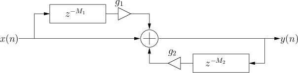
- The general comb filter is given by the difference equation
where and  are the feedforward and feedback coefficients,
respectively.
are the feedforward and feedback coefficients,
respectively.
Figure 24:
Signal flow diagram for digital comb filters.
 |
``Mus 270a: Introduction to Digital Filters''
by Tamara Smyth,
Department of Music, University of California, San Diego.
Download PDF version (filters.pdf)
Download compressed PostScript version (filters.ps.gz)
Download PDF `4 up' version (filters_4up.pdf)
Download compressed PostScript `4 up' version (filters_4up.ps.gz)
Copyright © 2019-02-25 by Tamara Smyth.
Please email errata, comments, and suggestions to Tamara Smyth<trsmyth@ucsd.edu>