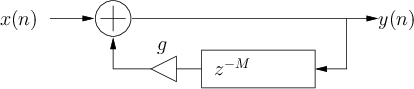
What happens when we multiply the output of a delay line
by a gain factor  then feed it back to the input?
Figure 19:
The signal flow diagram of a comb filter.
 |
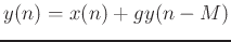
The difference equation for this filter is
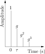
If the input to the filter is an impulse
the output (impulse response) will be ...
Figure 20:
Impulse response for filter
 .
.
 |
``Mus 270a: Introduction to Digital Filters''
by Tamara Smyth,
Department of Music, University of California, San Diego.
Download PDF version (filters.pdf)
Download compressed PostScript version (filters.ps.gz)
Download PDF `4 up' version (filters_4up.pdf)
Download compressed PostScript `4 up' version (filters_4up.ps.gz)
Copyright © 2019-02-25 by Tamara Smyth.
Please email errata, comments, and suggestions to Tamara Smyth<trsmyth@ucsd.edu>